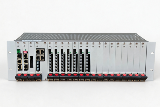
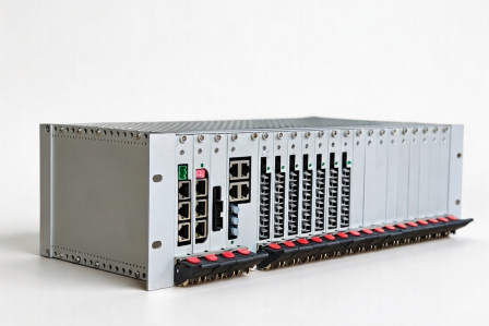
The Multi-Channel H-Bridge Controller is a high-reliability digital control core for the magnet power supply systems of nuclear fusion devices. It was originally designed for the Poloidal Field (PF) coil power supply of the SUNIST-2 device, where it controls the state of the PF power supply H-bridges in order to precisely regulate the discharge waveform. The design is portable and can also be applied to other high-power pulsed power supply control scenarios, including CS power supplies, MC power supplies, and plasma acceleration. The product uses a modular chassis-based design with an FPGA as its control core, and comprises six functional modules: the FPGA main control module, the communication module, the power supply module, the link module, the optical-port signal output module, and the signal acquisition module. All modules are interconnected through a backplane and are hot-swappable, which ensures reliable power delivery and signal transmission while keeping maintenance and upgrades convenient. In addition to controlling the output current waveform, the controller performs multi-point acquisition and real-time monitoring of voltage and current signals at various points in the power supply. The acquired signals are compared against preset thresholds to determine whether a fault exists at each monitoring point, thereby achieving fault localization and real-time protection, and safeguarding both the electrical supply and the equipment.
Composition
The complete controller uses a chassis-based structure in which the individual boards are interconnected through a backplane and are hot-swappable. The main boards are listed below:
| Board | Function |
| Control board | ZYNQ 7020 core board |
| ADC acquisition board | Performs analog-to-digital acquisition of voltage / current signals |
| Optical-port board ×7 | Each board contains a drive circuit and 6 optical ports |
| Power supply board | Supplies power to all boards |
| Parameter | Specification |
| Control core | ZYNQ 7020 |
| System architecture | Modular chassis-based |
| Optical signal transmission | Electrical signals are converted to optical signals through the optical ports for output, providing high isolation voltage and interference immunity, and remaining unaffected by transmission distance or speed |
| ADC acquisition | Two groups in total: 4 channels (24-bit) and 16 channels (12-bit) |
| Protective action | PWM is latched off when a threshold is exceeded; if any power supply experiences overvoltage or overcurrent, the PWM of both power supply sets is latched off |
| Trigger input | Optical-port trigger signal |
| Host communication | Modbus RTU / RS485 |
| Fault indication | 16-channel LED |
| Supported discharge modes | Current feedback / voltage feedback / no feedback |
| Multi-supply coordinated response | Switching of the discharge state between different power supplies is completed within milliseconds |
| Supply voltage | 220 VAC |
| Dimensions | 3U chassis (length × width × height: 44 × 20 × 13.5 cm; 48 × 20 × 13.5 cm including mounting ears) |
| Delivery form | Chassis-based unit |
The product is suitable for digital control and protection of nuclear fusion devices and high-power pulsed power supplies. Typical application scenarios include:
1. Poloidal Field (PF) coil power supply control
2. Central Solenoid (CS) power supply control
3. MC power supply control
4. Plasma acceleration power supply control
5. Real-time coordinated control of multiple power supplies
6. Triggering, fault detection, and protection of high-current IGBT converters
7. Nuclear fusion plasma experiments and discharge systems